6.3 DMT Modulation via Matlab/Octave Code
In DMT, the channel partition is obtained with a DFT (more specifically, with an FFT) of size . Several QAM and PAM symbols are grouped to create a DMT symbol represented by a vector Xk with elements , which is interpreted as in frequency domain. Conceptually, the subcarriers (sinusoids) are scaled by the elements of via an inverse FFT, as in Eq. (D.21), to obtain the time-domain samples xn. For example, the first element of this vector is the substream information that will be transmitted at the DC tone ( in Eq. (D.41)).
In Matlab/Octave the modulation can be done with xn=ifft(Xk), but it is convenient to use an orthonormal definition of the pair FFT / IFFT, as explained via Eq. (D.44).
Before sending the time-domain samples to the DAC chip, the DMT modulator places a copy of the
cpN=4L_cp=2L_cp=3L_cpD
Figure 6.1 depicts a DMT system. The FEQ block is the frequency equalizer that, for each tone, compensates the effect of the channel . Given an estimate of the channel and eventually of the noise, the role of a FEQ algorithm to remove the deleterious influence of the channel. This can be done by multiplying each received symbol by .
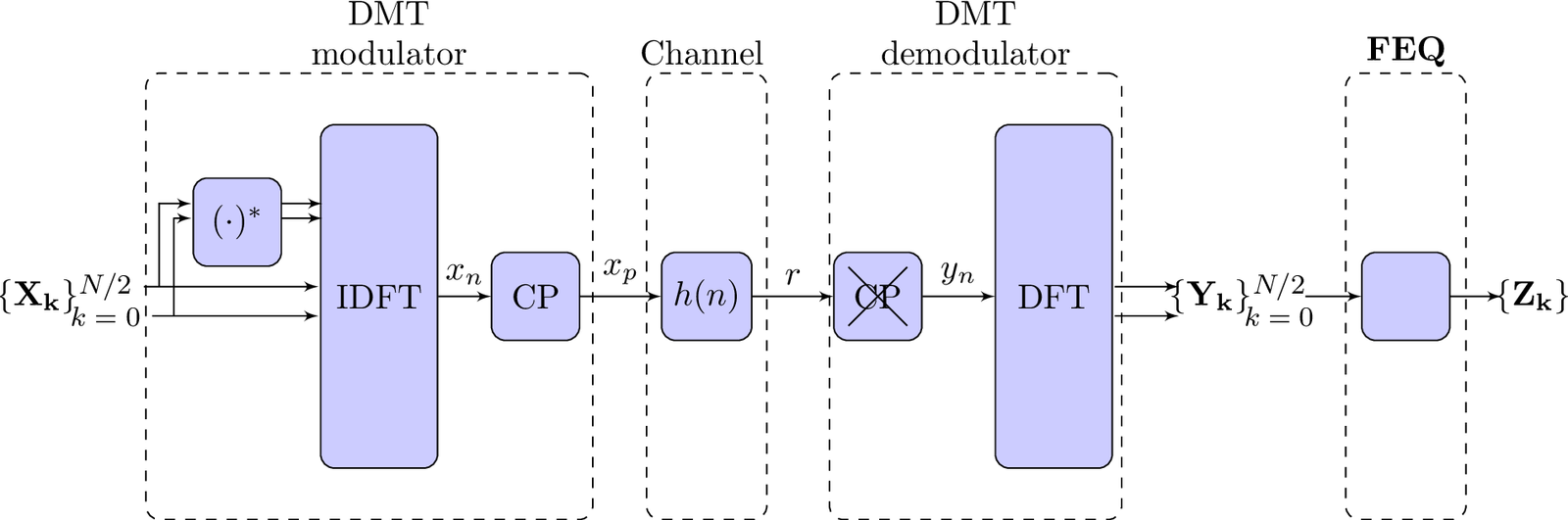
Because the system is designed such that the tones are independent, the fundamental DMT equation is
|
| (6.2) |
where and are the channel frequency response and noise at the -th tone, respectively. This equation is valid under the assumption of a perfect channel partition.
Listing 6.1 shows how to transmit one DMT symbol using IFFT / FFT over a channel with impulse response , which corresponds to a dispersion of samples. In this case, it was adopted
cp=2
1%Transmit a single DMT symbol with the channel relaxed
2N=4 %number of FFT points
3h=[0.6 1.2 0.3] %channel impulse response
4Hk = fft(h,N) %find the channel freq. response at tone frequencies
5Gk = 1 ./ Hk %frequency equalizer (FEQ): assume a perfect estimate
6Xk=[-1 -1-1j 3 -1+1j] %DMT symbol, transmitted information
7xn=ifft(Xk)*sqrt(N)  %adopt orthonormal FFT (Parseval applies)
8xp=[xn(N-1) xn(N) xn]  %add cyclic prefix with Lcp=2 samples
9r=conv(xp,h) %transmit over channel via linear convolution
10yn=r(3:6)    %take cyclic prefix out
11Yk=fft(yn)/sqrt(N)  %an orthonormal FFT has been adopted
12Zk = Yk .* Gk  %estimated symbols, after FEQ, compare with Xk
Note in Listing 6.1 that a unitary (orthonormal) IFFT / FFT pair was used for modulation and demodulation. This is not strictly required and any valid DFT pair could be used, given that the output and input powers will be controlled by the analog front end electronics.
Note that, besides its usage for demodulation, the FFT is also adopted in Listing 6.1 to obtain the values Hk of the channel frequency response. These values correspond to sampling the channel DTFT and, to be properly estimated, the FFT normalization factors are and , as explained in Eq. (D.44).
If the channel frequency response is 0 at some tone, it is not possible to send information via this tone. Recalling Eq. (E.53), if the channel has , its system function is , which has a zero gain at the Nyquist frequency. Listing 6.1 can be modified to use this channel and demonstrate that the information sent at tone in this case cannot be recovered. Similarly, a channel with has a zero gain at DC and the tone should not be used in this case.
Listing 6.2 shows how to consecutively transmit two DMT symbols, indicating how the channel memory must be taken into account when using the routine filter in Matlab/Octave, as discussed in Application E.7.
1%transmit two DMT symbols (first with the channel relaxed)
2N=4 %number of FFT points
3h=[0.2 0.3 0.9] %channel impulse response
4D=length(h)-1; %channel dispersion
5L=D; %cyclic prefix length (minimum recommended value)
6Hk = fft(h,N) %channel freq. response
7Gk = 1 ./ Hk %frequency equalizer (FEQ): perfect estimate
8ch_memory = zeros(1,D);  %initial channel memory zeroed
9%Transmit 1st DMT symbol
10Xk=[-1 -1-j 3 -1+j] %DMT symbol, transmitted information
11xn=ifft(Xk)*sqrt(N)  %adopt orthonormal FFT
12xp=[xn(N-L+1:end) xn]  %add cyclic prefix with L samples
13[r,ch_memory]=filter(h,1,xp,ch_memory)%update channel mem.
14yn=r(L+1:end)    %take CP out
15Yk=fft(yn)/sqrt(N)  %an orthonormal FFT has been adopted
16Zk = Yk .* Gk  %estimated symbols, after FEQ
17ErrorInSymbols1 = Xk-Zk %check if symbols were recovered
18%Transmit 2nd DMT symbol
19Xk=[3 2-j 7 2+j] %info to be transmitted at 2nd symbol
20xn=ifft(Xk)*sqrt(N)  %adopt orthonormal FFT
21xp=[xn(N-L+1:end) xn]  %add cyclic prefix with L samples
22[r,ch_memory]=filter(h,1,xp,ch_memory)%update channel mem.
23yn=r(L+1:end)    %take CP out
24Yk=fft(yn)/sqrt(N)  %an orthonormal FFT has been adopted
25Zk = Yk .* Gk  %estimated symbols, after FEQ
26ErrorInSymbols2 = Xk-Zk %check if symbols were recovered
Observe that X in Listing 6.1 has the required Hermitian symmetry to generate a real-valued DMT signal.
Assuming the sampling frequency (the rate that the transmitted DAC chip works) is , the DFT tone spacing is as illustrated in Table D.6. Hence, the carrier frequency of the -th tone is given by Eq. (D.41): .
While some standardized OFDM systems use the same number of bits for all tones, DMT-based DSL systems for example allocate more bits to tones with larger SNR. In other words, for DSL, is proportional to . The process of choosing is known as bit-allocation and will be discussed later. Before that, Listing 6.3 shows details about DMT with a given bitloading and the use of distinct constellations.
1N=8 %number of FFT points
2h=[2 1 0 3]; %channel impulse response
3%bitloading is [1, 2, 3, 3, 2] bits per symbol
4%1) Design constellations
5M = 2; pamconstM2 = -(M-1):2:M-1; %2-PAM
6M = 4; pamconstM4 = -(M-1):2:M-1; %4-PAM
7M = 4; qamconstM4 = ak_qamSquareConstellation(M); %4-QAM
8M = 8; qamconstM8 = ak_qamSquareConstellation(M); %8-QAM
9%Bitstream is B={0 11 101 100 10}
10X0 = pamconstM2(bin2dec('0')+1); %find the symbol
11X1 = qamconstM4(bin2dec('11')+1);
12X2 = qamconstM8(bin2dec('101')+1);
13X3 = qamconstM8(bin2dec('100')+1);
14X4 = pamconstM4(bin2dec('10')+1);
15X5 = conj(X3);  %impose the Hermitian symmetry
16X6 = conj(X2);
17X7 = conj(X1);
18%Compose DMT symbol to be modulated and transmitted:
19Xk=[X0 X1 X2 X3 X4 X5 X6 X7]
20L = 3; %length of cyclic prefix = channel dispersion
21xn=ifft(Xk)*sqrt(N)  %adopt orthonormal FFT
22xp=[xn(N-L+1:N) xn]  %add cyclic prefix (CP)
23r=conv(xp,h) %transmit: convolve with channel response h
24yn=r(L+1:L+N) %take CP out and keep N information samples
25Yk=fft(yn)/sqrt(N)  %an orthonormal FFT has been adopted
26Hk=fft(h,N);%channel frequency response with N-points FFT
27Gk = 1 ./ Hk %frequency equalizer FEQ
28Zk = Yk .* Gk  %decoded symbols
29%discard negative frequencies and demodulate
30b0 = dec2bin(ak_pamdemod(real(Zk(1)),2))
31b1 = dec2bin(ak_qamdemod(Zk(2),4))
32b2 = dec2bin(ak_qamdemod(Zk(3),8))
33b3 = dec2bin(ak_qamdemod(Zk(4),8))
34b4 = dec2bin(ak_pamdemod(real(Zk(5)),4))
35receivedBitstream=[b0 ' ' b1 ' ' b2 ' ' b3 ' ' b4]
36disp('Transmitted bitstream was B={0 11 101 100 10}')
The next section discusses how the rate can be calculated in multicarrier systems.