2.8 Simple Binary Modulations: ASK, FSK and PSK
PAM is a baseband signal with its power concentrated near DC. Three simple passband signals are now briefly discussed. These signals convey information by using distinct values of a) amplitude, b) frequency or c) phase and are called amplitude-shift keying (ASK), frequency-shift keying (FSK) and phase-shift keying (PSK), respectively. The term “keying” is used because the modulation can be implemented by manipulating the carrier via switch(es) turning on and off.
In some texts, ASK modulation is called PAM, while here PAM corresponds to a baseband signal and ASK is a passband signal obtained by frequency upconversion of a PAM signal.
To simplify the discussion, this section assumes binary systems, in which there are only symbols, representing bits 0 and 1 via waveforms and , respectively. The system designer can choose and such that their duration in seconds is different (shorter or longer) than . It is assumed here that both and have exactly non-zero samples, such that the oversampling is also the number of samples per symbol in this case. There are very efficient ways of generating the three signals but Listing 2.10 illustrates how to obtain binary ASK, FSK and PSK modulations emphasizing clarity not computational cost. For example, alternatively, the ASK and PSK could be obtained by multiplying a suitable PAM signal by the carrier sinusoid and the FSK by using two sinusoids of distinct frequencies.
1function outputWaveform = ak_simpleBinaryModulation( ...
2    modulation, bits)
3% function outputWaveform = ak_simpleBinaryModulation(
4%   modulation, bits)
5%Inputs: modulation -> use 'ASK', 'FSK' or 'PSK'
6%        bits, generate e.g. with b = floor(2*rand(1,10))
7%Example:
8% s = ak_simpleBinaryModulation('ASK',floor(2*rand(1,20)))
9Fs = 16000; %D/A conversion frequency in Hz
10Rsym = 500; %signaling (symbol) rate in bauds
11L = round(Fs/Rsym); %oversampling factor
12N = length(bits); %number of random bits to be transmitted
13n=0:L-1; %index to generate S samples of the waveforms
14%Design the pair of waveforms to represent bits 0 and 1:
15switch modulation
16    case 'ASK'
17        A0 = 0; A1 = sqrt(8); w = pi/16;
18        s0 = A0 * cos(w * n); s1 = A1 * cos(w * n);
19    case 'FSK'
20        w0 = pi/16; w1 = 3*pi/16; A = 2;
21        s0 = A * cos(w0 * n); s1 = A * cos(w1 * n);
22    case 'PSK'
23        w = pi/16; A = 2;
24        s0 = A * cos(w * n);
25        s1 = -A * cos(w * n); %same as s1=A*cos(w*n + pi)
26end
27%Generate whole waveform by selecting the waveform segment
28outputWaveform = zeros(1,N*L); %pre-allocate space
29for i=1:N
30    bitTx = bits(i); %get one bit
31    startSample = 1+(i-1)*L; %place to output signal
32    if bitTx == 1 %choose segment for bit 1 or 0
33        outputWaveform(startSample:startSample+L-1) = s1;
34    else
35        outputWaveform(startSample:startSample+L-1) = s0;
36    end
37end
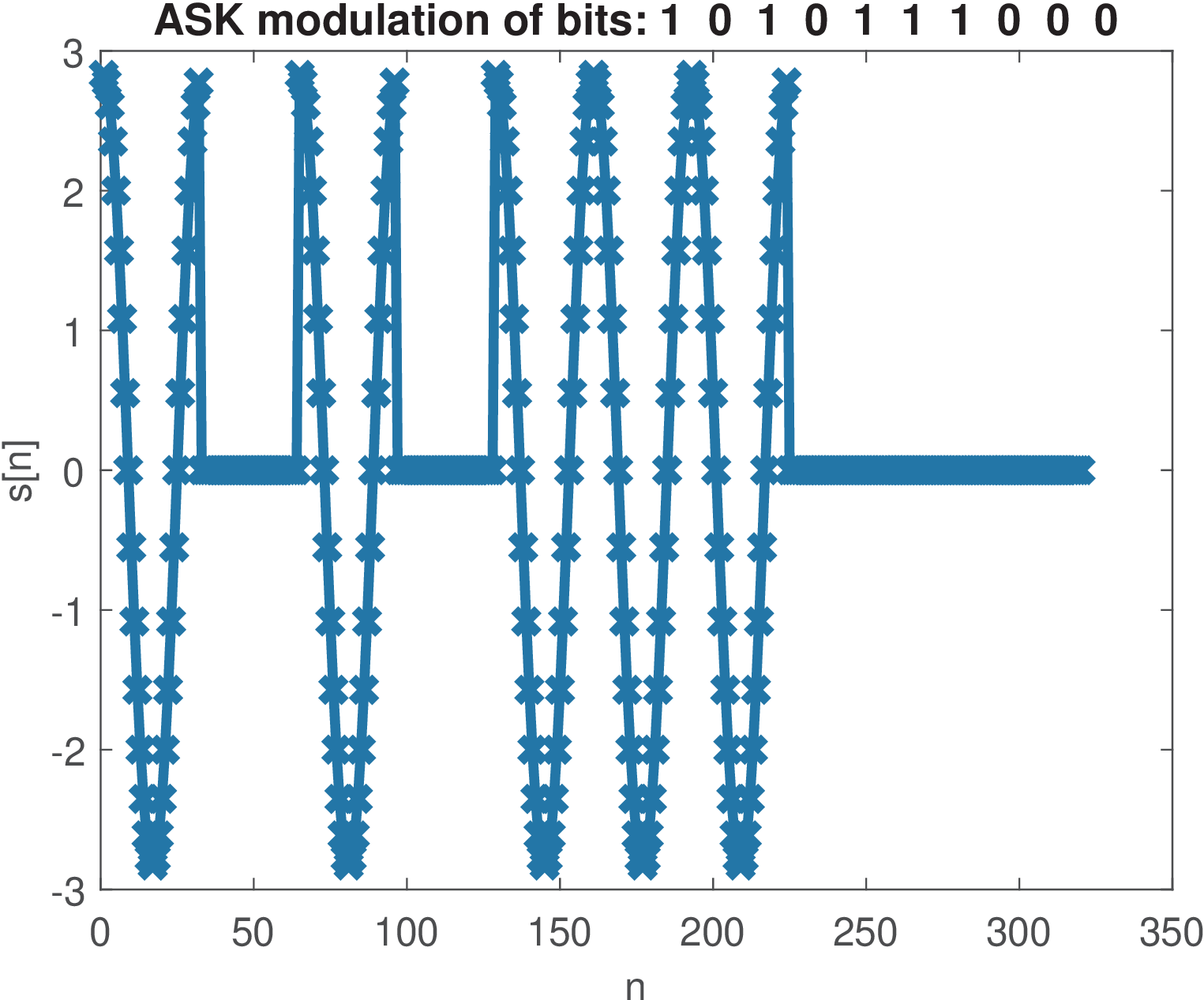
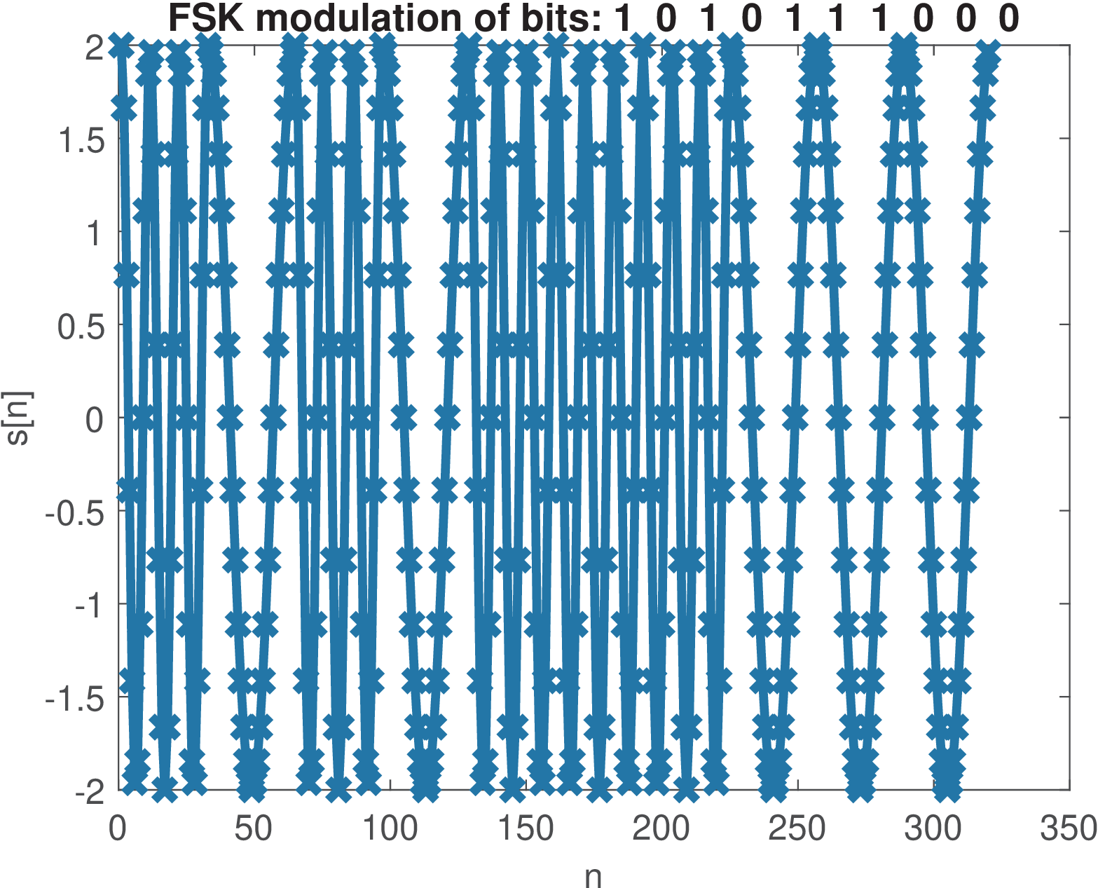
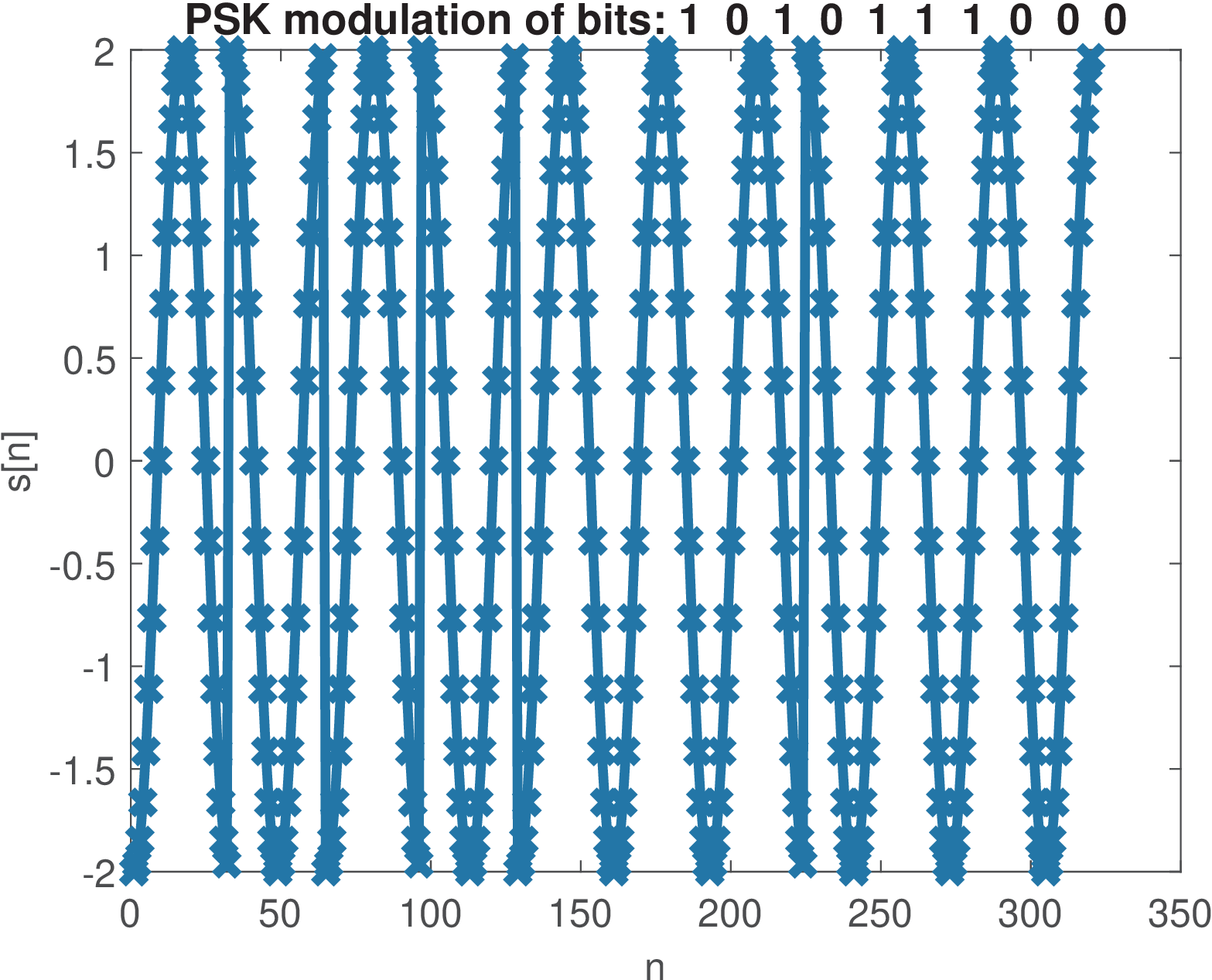
Figure 2.12 was generated with the commands below and show a segment of an ASK waveform.
1N=10; %number of bits
2bits=floor(2*rand(1,N)); %generate N random bits
3plot(ak_simpleBinaryModulation('ASK', bits),'x-')
In this case, ASK was generated with samples per symbol. One can note that the transmitted bit indicates the amplitude of a cosine waveform.
Similarly, Figure 2.13 and Figure 2.14 were generated for FSK and PSK modulations, respectively. It should be observed that, in PSK, has a phase shift of rad with respect to the phase of . The ASK and PSK modulations use a cosine of frequency rad, which corresponds (see Eq. (C.37)) to rad/s or 500 Hz. This FSK represents bits 0 and 1 by cosines of 500 and 1500 Hz, respectively. For all three modulations the average power is 2 W. This requires the peak amplitude of ASK to be larger than the other two modulations to compensate the instantaneous power being zero over the duration of the respective bit (bit 0 in Figure 2.12).