3.17 Advanced: Multirate Processing
Many modern DSP systems adopt distinct sampling rates along the processing chain, using interpolators and decimators. Two basic blocks of these multirate processing systems are the upsampler and downsampler.
3.17.1 Upsampler and interpolator
The upsampler has an output for any that is an integer multiple of and 0 otherwise. It is represented by
Note that distinct indexes and are used to emphasize the sampling rates are not the same.
The upsampling by is not a time-invariant operation (in spite of being linear), so the system is not LTI. When the input is a WSS process, the output process cannot be assumed WSS.
The Fourier transform of the upsampler output is given by:
|
| (3.98) |
which corresponds to scaling the abscissa by the factor such that is a compressed version40 of .
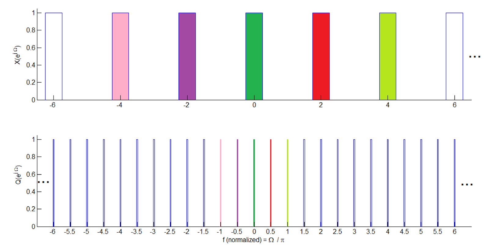
Figure 3.66 provides an example where the original spectrum is an ideal lowpass filter with cutoff frequency rad. After upsampling by , the resulting has not a lowpass spectrum anymore. In fact, the new “high frequency” components in are required to enable the amplitudes of the upsampler output to vary from/to zero between two original samples of the (relatively “smooth”) input .

Notice that there is no aliasing or change in spectrum amplitude involved in this process, but within rad, has versions of what was the original in the range rad as emphasized in Figure 3.67. In this example, with , the equivalent of four replicas of the original spectrum can be found within rad: the ones centered at and half of the replicas in and 1.

The autocorrelations and of the signals at, respectively, the input and output of an upsampler are related by
|
| (3.99) |
Assuming the entire bandwidth of the input is of interest, in order to eliminate all images within the interval except the one centered at (DC), a lowpass filter should have a stopband starting at . Otherwise, imaging will occur. Hence, an interpolator is composed of an upsampler and a lowpass filter, which is represented by
3.17.2 Downsampler and decimator
Meanwhile, the downsampler can be represented by
and has an output . Its spectrum can be expressed as:
|
| (3.100) |
In other words, the spectrum of the downsampled signal is the sum of stretched versions of the spectrum of the input signal .
As discussed in Example 1.5, the transformation of the independent variable corresponds to stretching the frequency axis by and shifting this intermediate result by rad. As indicated in Eq. (3.100), these individual versions are summed and the result is scaled by .
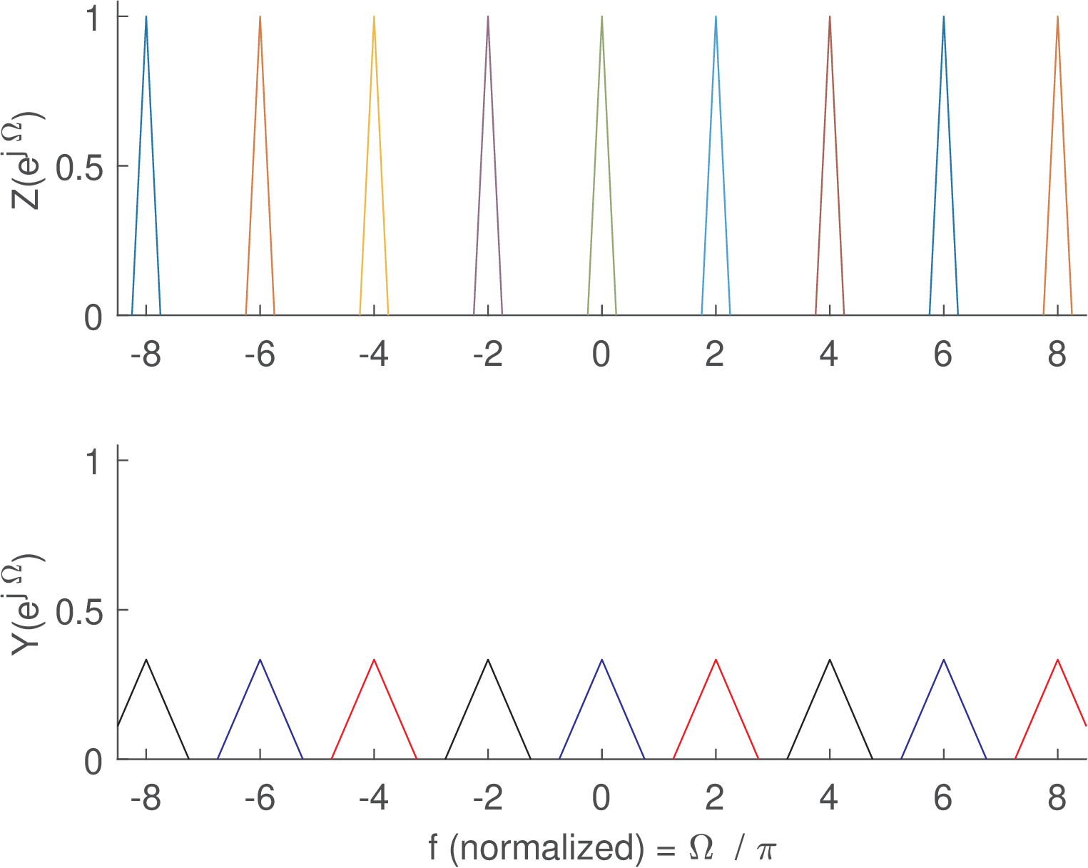
Figure 3.68 illustrates an example in which the original spectrum is downsampled by . As indicated by Eq. (3.100), is composed by parcels and each one represented by one color in Figure 3.68.

If one considers a single parcel , it can be observed that a parcel itself is not periodic in , as required for any discrete-time signal spectrum. For example, (in blue) alone does not have a period of . The replica at rad of the original spectrum is shifted to in and, consequently, does not have a replica at nor , but only at and multiples. But when the parcel is combined with (in red) and (in black), the resulting spectrum indeed indicates that has a period of .
Since the maximum frequency that can be represented after downsampling is reduced by a factor of , any frequency beyond in the input will be aliased into the central period of the downsampled signal, as indicated by the replicas in Eq. (3.100). Hence, a decimator is composed of an anti-alising filter designed with stopband edge at and a downsampler, as illustrated in
Note that an interpolator uses a lowpass filter after the upsampling operation to combat imaging, while a decimator uses the lowpass filter before downsampling in order to control aliasing.