3.9 Advanced: Filtering technologies: Surface acoustic wave (SAW) and others
There are several technologies to build an electronic filter. The options include ceramic, microelectromechanical system (MEMS), yttrium iron garnet (YIG), SAW and many others. Even if the scope is reduced to radio-frequency (RF) communications, the diversity of filters is huge. Consequently, parameters such as the Q-factor, center frequency and insertion loss (which is the inverse of the insertion gain , as discussed in Section A.25), vary widely. This section provides some practical examples.
Example 3.11. Performance of commercial SAW filter. Figure 3.26 illustrates the typical performance of a commercial SAW filter12 with some of its specifications listed in Table 3.4. The insertion gain is shown in Figure 3.26 at 1 and 10 dB per division (div) at the left plot and superimposed (at 1 dB per division) to the group delay at the right plot.
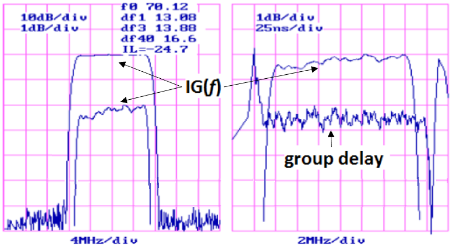
As also indicated in Table 3.4, Figure 3.26 indicates that df1, df3 and df40 are the bandwidths considering the attenuation at 1, 3 and 40 dB, respectively, with values 13.08, 13.88 and 16.6 MHz. The insertion loss at MHz is 24.7 dB. The group delay plot only shows the variation at the order of ns, but Table 3.4 indicates the delay as 1.6 s. As indicated in Section A.25, is sometimes called IL and Figure 3.26 uses a negative IL to express that the filter attenuates the power by 24.7 dB as properly expressed in Table 3.4.
| Parameter | Minimum | Typical | Maximum |
| Center frequency at C ( or f0, MHz) | 69.8 | 70 | 70.2 |
| Insertion loss at (IL, dB) | - | 24.7 | 28.0 |
| 1-dB bandwidth (df1, MHz) | 12.75 | 13.0 | - |
| 3-dB bandwidth (df3, MHz) | 13.0 | 13.8 | - |
| 40-dB bandwidth (df40, MHz) | - | 16.6 | 17.1 |
| Passband variation (ripple, dB) | - | 0.5 | 0.6 |
| Group delay variation (ns) | - | 25 | 50 |
| Absolute delay (s) | - | 1.6 | - |
The Q-factor of the filter depicted in Figure 3.26 is and provides more than 60 dB of attenuation at the stopband. Building such (relatively) highly-selective filters is easier when the center frequency is fixed than when it has to vary, for tuning purposes. For example, the filter of Figure 3.26 is supposed to operate with MHz, which is an intermediate frequency (IF) used in wireless signal reception. When a receiver has to operate over a frequency range, a common strategy is to pre-select the frequency band of interest using a so-called RF-filter with center frequency (e. g., 2.1 GHz) and convert it via frequency shifting to the IF (e. g., 70 MHz), when it is then better filtered and further processed.
A common IF for broadcast AM radio is kHz, which motivates the next filter example.
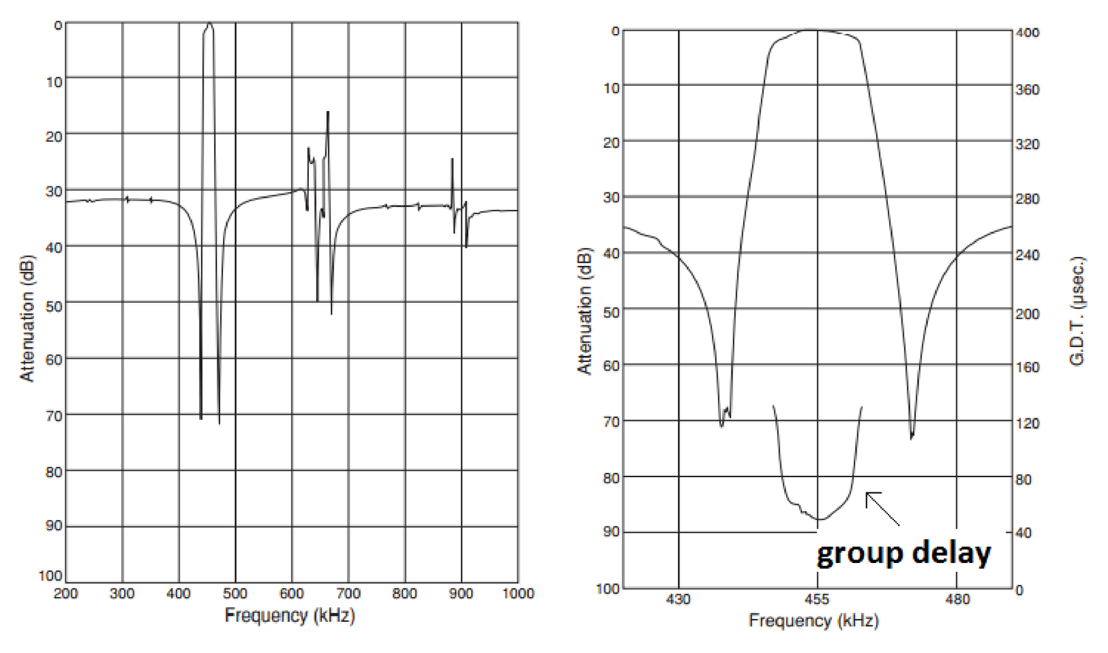
Example 3.12. Commercial ceramic filter. Figure 3.27 illustrates the performance of a commercial ceramic filter13 that can be used with an IF of 455 kHz and has some specifications listed in Table 3.5. Note that this filter’s stopband is not flat, especially within the range from 600 to 700 kHz. This makes the specifications harder to interpret than for an ideal bandpass filter.
| Parameter | Value |
| Center frequency (kHz) | |
| Minimum 6-dB bandwidth (kHz) | |
| Maximum stop bandwidth, within 40 dB (kHz) | |
| Minimum stopband attenuation within kHz (dB) | 27 |
| Maximum insertion loss (at minimum loss point, dB) | 6 |
| Maximum ripple within kHz (dB) | 1.5 |
Caution has to be exercised when interpreting the “Maximum stop bandwidth” in Table 3.5, which indicates the filter attenuates 40 dB at the end of a band centered on and with a bandwidth of approximately 30 kHz. But this attenuation then decreases. According to Table 3.5, an attenuation of at least 27 dB is guaranteed only within kHz.