A.25 Insertion loss and insertion frequency response
A system is often composed by the interconnection of several blocks and it is of interest to know how a signal is attenuated (or amplified!) as it passes through the blocks. The insertion loss (IL) is widely used to characterize the loss in power, for example, of a transmission line or a circuit. This section discusses the IL of a generic two-port network (or quadripole), which is any four-terminal network called here device under test (DUT). Material about IL in specific applications can be found elsewhere. For example, in [ANS03] (more specifically, “C.3.1.7 Relationship of transfer function and insertion loss”) there is an interesting discussion of IL in the DSL systems context.
IL estimation is based on a smart strategy: measure the system output with and without the DUT, with the IL being the attenuation imposed by the DUT.
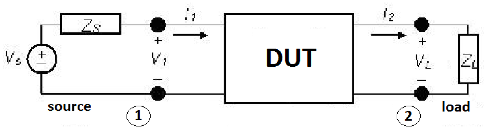
Figure A.34 depicts a setup for measuring the insertion loss of a DUT. The behavior without the DUT is obtained by removing it (i. e., directly connecting the pairs of terminals 1 and 2, and measuring the power over the load, which in this case will be denoted as . Then, the behavior with the DUT is obtained by inserting it and again measuring the power over the load, which will be denoted as . The insertion loss in dB is defined as
|
| (A.115) |
and is often given in dB:
|
| (A.116) |
For example, a passive optical device that splits the input into two output signals could have an IL of 4 dB per output, consisting of the ideal 3 dB IL for splitting the power in halves plus an excess loss of 1 dB per port.
If the system behavior varies with frequency, can be measured and reported over the frequency range of interest. Besides, in case the DUT amplifies its input, one can use the insertion gain instead.
Another alternative definition of IL uses the voltage over the load. Repeating the procedure of removing and then inserting the DUT, the measured values of are denoted as and , respectively. In this case and assuming frequency-dependence, IL can be written as
|
| (A.117) |
The “insertion” trick (measuring with and without the DUT) can be used to obtain parameters other than the IL. For example, in some situations it is inconvenient to deal with (or difficult to measure) the frequency response directly because it depends on the source and load impedances. In these cases, it may be advantageous to measure the insertion frequency response
|
| (A.118) |
and convert it to when convenient and the source and load impedances are known. Note that Eq. (A.118) does not discard the phases of the measured voltages as in Eq. (A.117), and can be obtained for example with a network analyzer equipment.
Having , the frequency response relating the output voltage (with the DUT) to the input source voltage can be obtained as
|
| (A.119) |
When and can be considered constant over the frequency of interest, Eq. (A.119) is conveniently expressed as
|
| (A.120) |
itself is of interest in some applications. For example, when estimating the channel capacity of a DSL copper loop, is adopted instead of [ANS03].
The “insertion” procedure is used in many distinct scenarios but people tend to keep together the terms “insertion” and “loss”, instead of using only the former. For example, some authors (e. g. [Cio10] and in Figure 3.26) call insertion loss to and report an attenuation as a negative value in dB. Others call the insertion frequency response of Eq. (A.120) as “insertion loss”, as in the FTW software, or “loop insertion gain transfer function” as in [ANS03].