2.4 Block Transforms
Generic block processing was presented in Section 1.4. This section discusses block transforms as a specific block-oriented signal processing, including DCT, DFT, and Haar transforms, which are among the most used transforms, together with the already presented KLT (or PCA).
In many signal processing tasks, it is useful to have two related transformations called a transform pair. One transform is the inverse of the other, with the inverse undoing the forward transform. When dealing with block transforms,5 one simply uses linear algebra (as detailed in Appendix A.12), and both transforms are simple matrix multiplications. The pair of transforms is defined by a pair of matrices. The matrices can be rectangular, as in lapped transforms,6 but most block transforms are defined by a pair of square matrices and and the jargon -point transform indicates their dimension. The inverse matrix is assumed to exist and can “undo” the transformation (and vice-versa). Here, the forward (or direct) transformation is denoted as
while the inverse transformation is denoted here as
|
| (2.10) |
The vector is called the transform of and the elements of are called coefficients. In this text, vectors are represented by bold lower case letters, but the vector with coefficients will be denoted by capital letters to be consistent with the jargon (unfortunately, vectors of coefficients such as can be confused with matrices, but the context will distinguish them).
An important concept is:
- The columns of the inverse transform matrix are called the basis functions (or basis vectors).
2.4.1 Advanced: Unitary or orthonormal transforms
A matrix with orthonormal columns is called unitary. The rows of a unitary matrix are also orthonormal. If one takes any pair of distinct rows or columns of the unitary matrix , their inner product is zero (they are orthogonal) and their norms are equal to one.
Unitary matrices are widely used in transforms because their inverse is simply the conjugate transpose as indicated in:
where denotes the Hermitian (conjugate transposition).
Considering Eq. (2.10), if the basis functions (columns of ) are orthonormal, then . Consequently, the rows of the direct transform are the complex-conjugate of the basis functions. Two important facts are:
- Forward: the -th coefficient of the forward transform is obtained by performing the inner product between and the -th basis function. Based on the definition of inner product for complex-valued vectors in Eq. (A.28), it is adopted the complex conjugate of the -th basis function. The larger is this coefficient magnitude, the better the -th basis function represents signal .
- Inverse: in the inverse transform , the column vector is obtained by the linear combination of the basis functions: the -th element (coefficient) in multiplies the -th column (basis function) of in a linear combination that generates .
Observing that the inverse of a unitary real matrix is its transpose
To get insight on why for a unitary , consider the elements of are real numbers, such that . The result of the product is the identity matrix (that is ), because the inner product between the rows of (columns of ) with the columns of is one when they coincide (main diagonal of ) and zero otherwise (due to their orthogonality). In other words, the inner products of columns of with themselves is the identity, given they are orthonormal. In case is complex-valued, one has via a similar reasoning.
The next paragraphs present the DCT transform, which can be used for both frequency analysis and coding.
2.4.2 DCT transform
An example of a unitary matrix transform very useful for coding is the discrete cosine transform (DCT). When , the corresponding matrices are
and, because in this case of a real-valued matrix :
for the direct and inverse transforms, respectively.
Because they have finite duration, one can represent the input signals of block transforms as vectors or sequences. For instance, the DCT basis function corresponding to the second column of could be written as
Considering that the first element is (first index in equations is zero, not one as in Matlab/Octave), an element of the -point inverse DCT matrix can be obtained by
where is a scaling factor that enforces the basis vectors to have unit norm, i. e., for and for .
Example 2.5. DCT calculation in Matlab/Octave. Listing 2.1 illustrates how the DCT matrices can be obtained in Matlab/Octave.
1function [A, Ainverse] = ak_dctmtx(N)
2% function [A, Ainverse] = ak_dctmtx(N)
3%Calculate the DCT-II matrix of dimension N x N. A and Ainverse are
4% the direct and inverse transform matrices, respectively. Ex:
5%  [A, Ainv]=ak_dctmtx(4); x=[1:4]'+1j; A*x, dct(x)
6Ainverse=zeros(N,N); %pre-allocate space
7scalingFactor = sqrt(2/N); %make base functions to have norm = 1
8for n=0:N-1 %a loop helps to clarify obtaining inverse matrix
9    for k=0:N-1 %first array element is 1, so use A(n+1,k+1):
10       Ainverse(n+1,k+1)=scalingFactor*cos((pi*(2*n+1)*k)/(2*N));
11    end
12end
13Ainverse(1:N,1)=Ainverse(1:N,1)/sqrt(2); %different scaling for k=0
14%unitary transform: direct transform is the Hermitian of the inverse
15A = transpose(Ainverse); %Matrix is real, so transpose is Hermitian
The matrices obtained with ak_dctmtx.m can be used to perform the transformations but this has only pedagogical value. There are algorithms for computing the DCT that are faster than a plain matrix multiplication. Check the functions dct and idct in Matlab/Octave and scipy.fftpack.dct in Python.
Example 2.6. The DCT basis functions are cosines of distinct frequencies. Figure 2.2 shows four basis functions of a 32-point DCT transform.
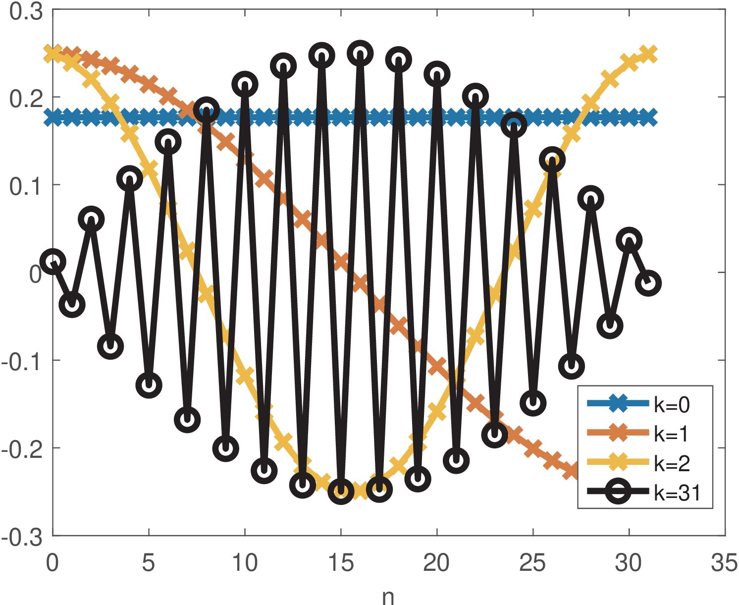
Figure 2.2 indicates that, in order to represent signals composed by “low frequencies”, DCT coefficients of low order (small values of can be used), while higher order coefficients are more useful for signals composed by “high frequencies”. For example, the commands:
return a vector X with all elements equal to zero but X(4)=28, which corresponds to (recall the first index in Matlab/Octave is 1, not 0). Using a larger will increase the frequency and the order of the corresponding DCT coefficient.
Example 2.7. Example of a DCT transformation. For example, assuming a 4-point DCT and , the forward transform can be obtained in this case with
In this case,
where represents the first (0-th) row of matrix . Similarly, is given by
and so on.
The previous expressions provide intuition on the direct transform. In the inverse transform, when reconstructing , the coefficient is the scaling factor that multiplies the -th basis function in the linear combination . Still considering the 4-point DCT, the inverse corresponds to
Note that and, consequently, the basis function is not used to reconstruct . The reason is that this specific basis function is orthogonal to and does not contribute to its reconstruction. As another example, the DCT coefficient indicates that a scaling factor equals to 5 should multiply the corresponding -th basis function in order to reconstruct the vector in time-domain.
Alternatively, the matrix multiplication can be described by a transform equation. For example, the DCT coefficients can be calculated by
and
As mentioned, the -th element (or coefficient) of can be calculated as the inner product of with the complex conjugate of the -th basis function. This can be done because the DCT basis functions are orthogonal among themselves, as discussed in Section A.12.3. The factors and are used to have basis vectors with norms equal to 1. The -th basis vector is a cosine with frequency and phase .
Section 2.10 discusses examples of DCT applications, including coding (signal compression). One advantage of adopting block transforms in coding applications is the distinct importance of coefficients. In the original domain, all samples (or pixels in image processing) have the same importance, but in the transform domain, coefficients typically have distinct importance. Hence, the coding scheme can concentrate on representing the most important coefficients and even discard the non-important ones. Another application of DCTs is in frequency analysis (finding the most relevant frequencies that compose a signal). But, in this application, the DFT is more widely adopted than the DCT.
2.4.3 DFT transform
As the DCT, the discrete Fourier transform (DFT) is a very useful tool to accomplish frequency analysis, where the goal is to estimate the coefficients for basis functions that are distinguished by their frequencies. The DFT is related to the discrete-time Fourier series, which also uses cosines and sines , , as basis functions, and will be discussed in this chapter. While the DCT uses cosines and its matrices are real, the DFT uses complex exponentials as basis functions.
Using Euler’s formula, Eq. (A.1), complex numbers provide a more concise representation of sines and cosines and the -th DFT basis function is given by
|
| (2.11) |
where expresses time evolution, as for the DCT. The value determines the angular frequency (in radians) of the basis function . Eq. (2.11) can be written as
|
| (2.12) |
which gives the -th value of the time-domain basis function .
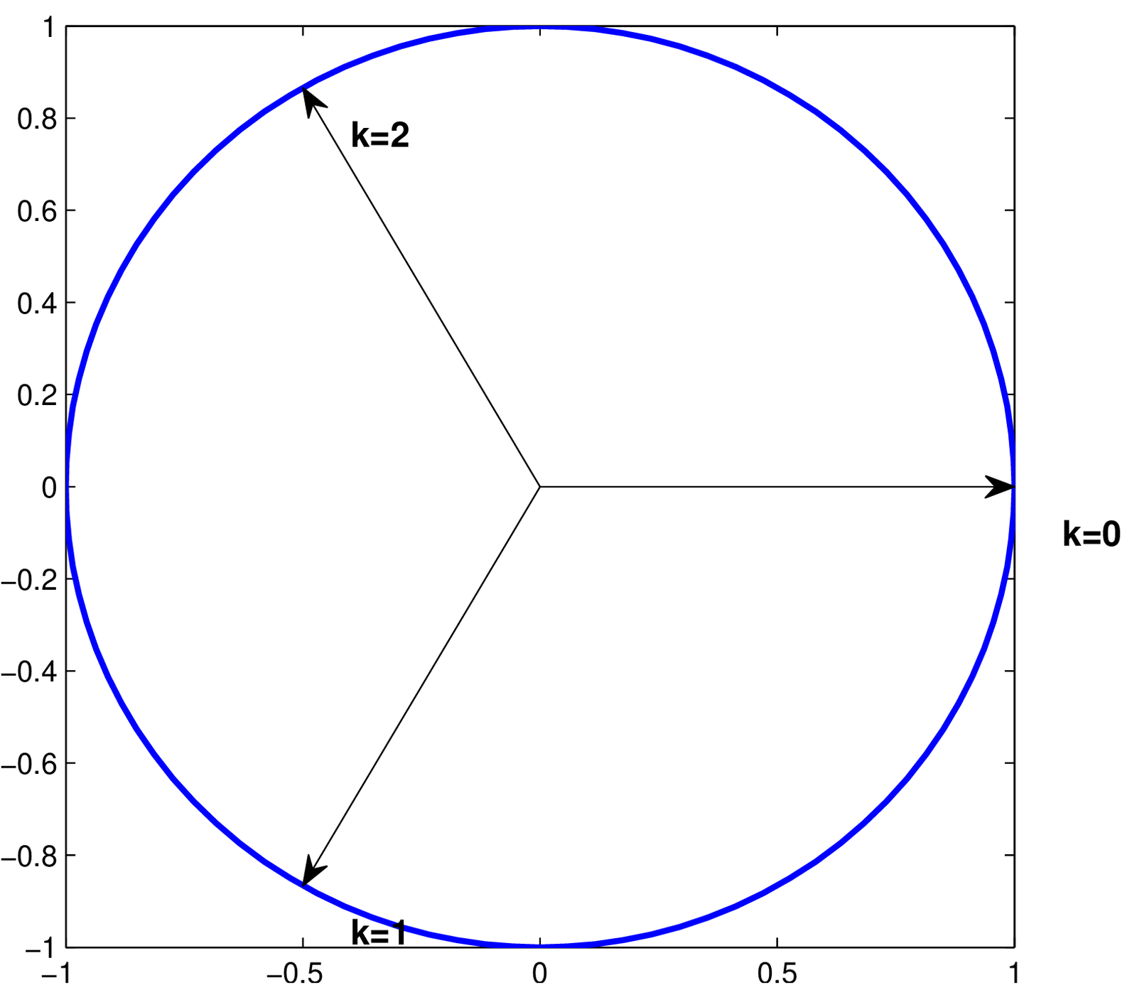
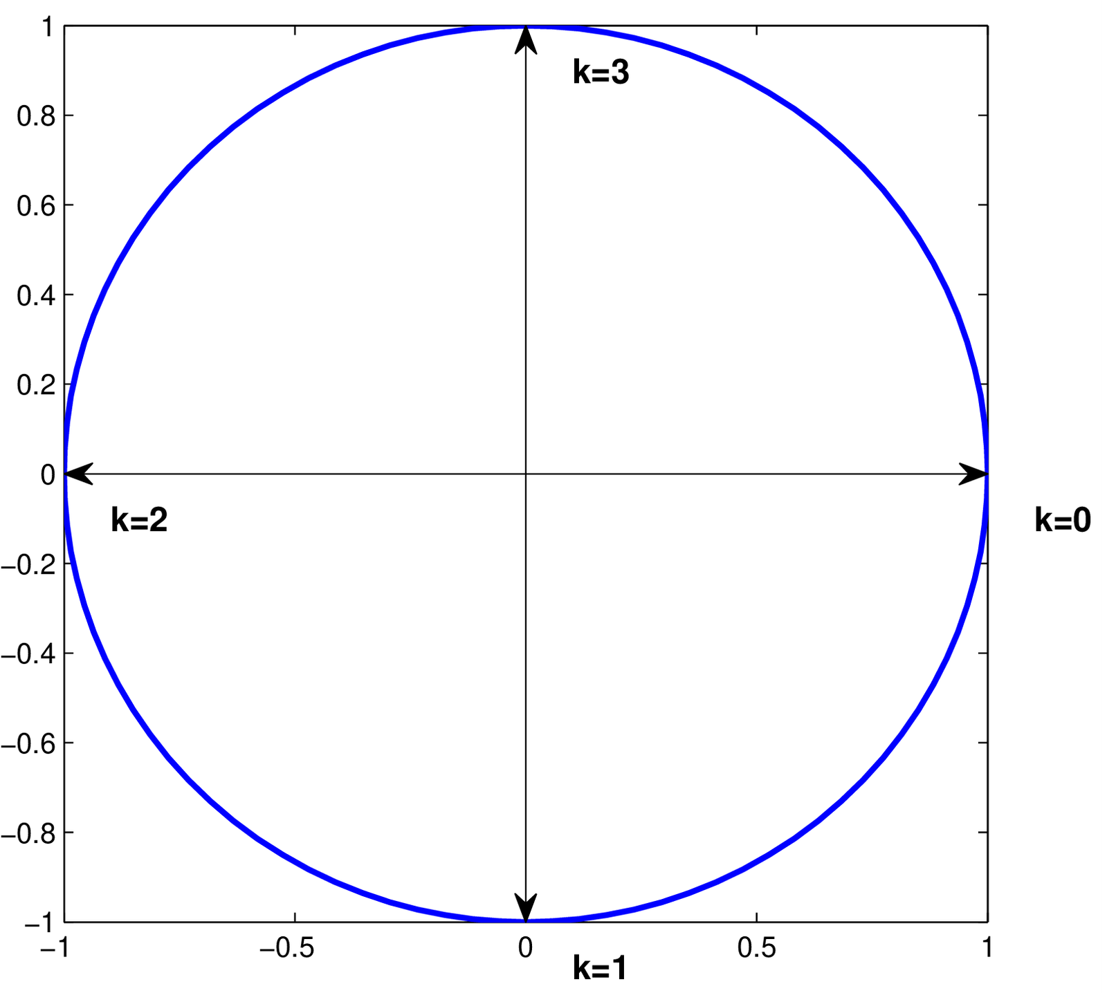
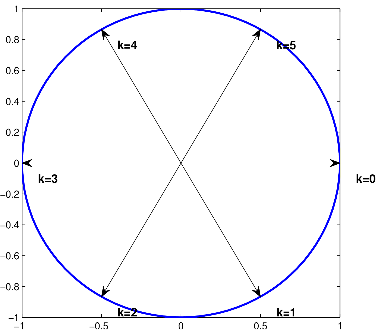
Hence, one can notice that the DFT operates with an angular frequency resolution , such that . For instance, considering , the resolution is rad and the DFT uses basis functions with angular frequencies and rad. This is depicted in Figure 2.3.
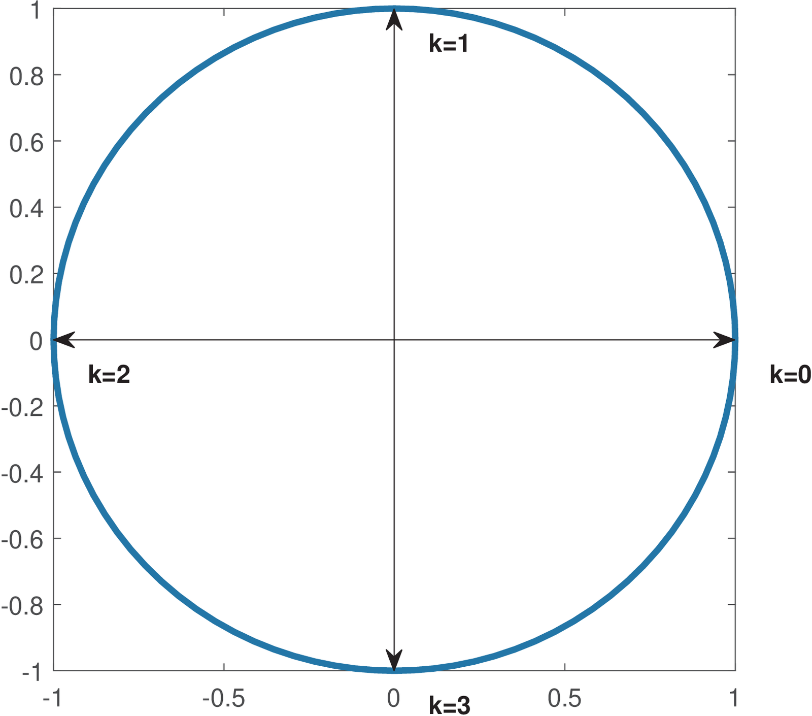
When in Figure 2.3, the angular frequency is rad, and the basis function is . The signal corresponds to the highest angular frequency rad among discrete-time signals, and this frequency is called Nyquist frequency, as discussed in Section 1.8.3.
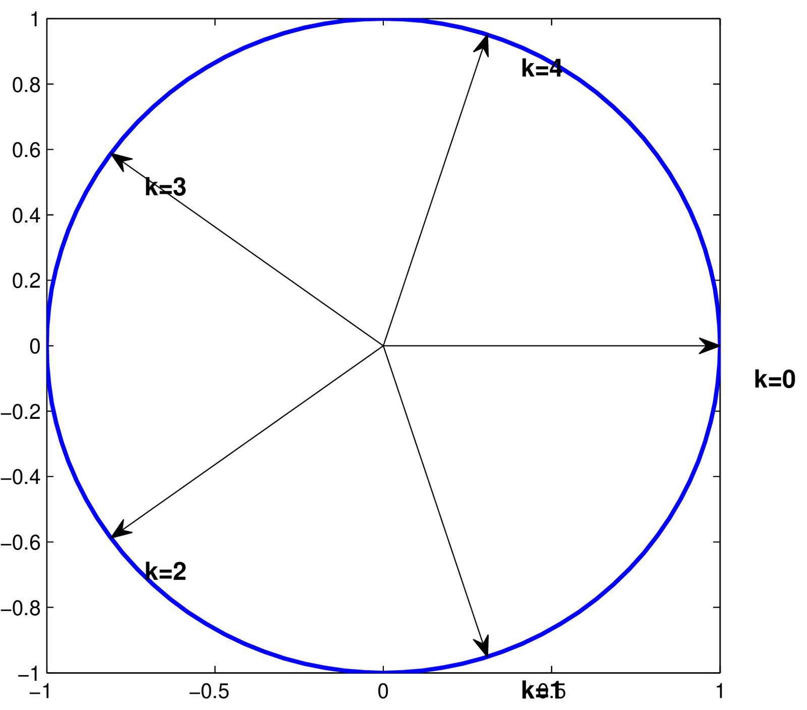
To complement Figure 2.3, which uses an even value , Figure 2.4 describes the DFT angular frequencies when .
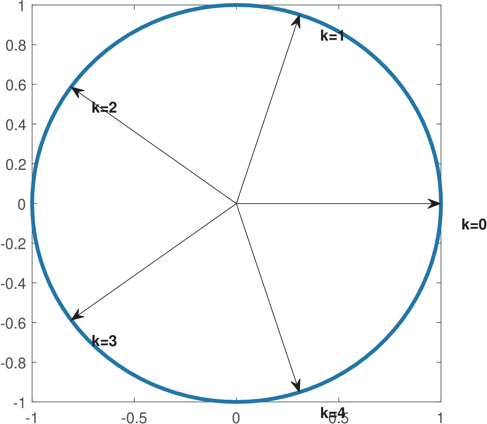
As depicted in Figure 2.4, when is odd, the Nyquist frequency rad is not used by the DFT.
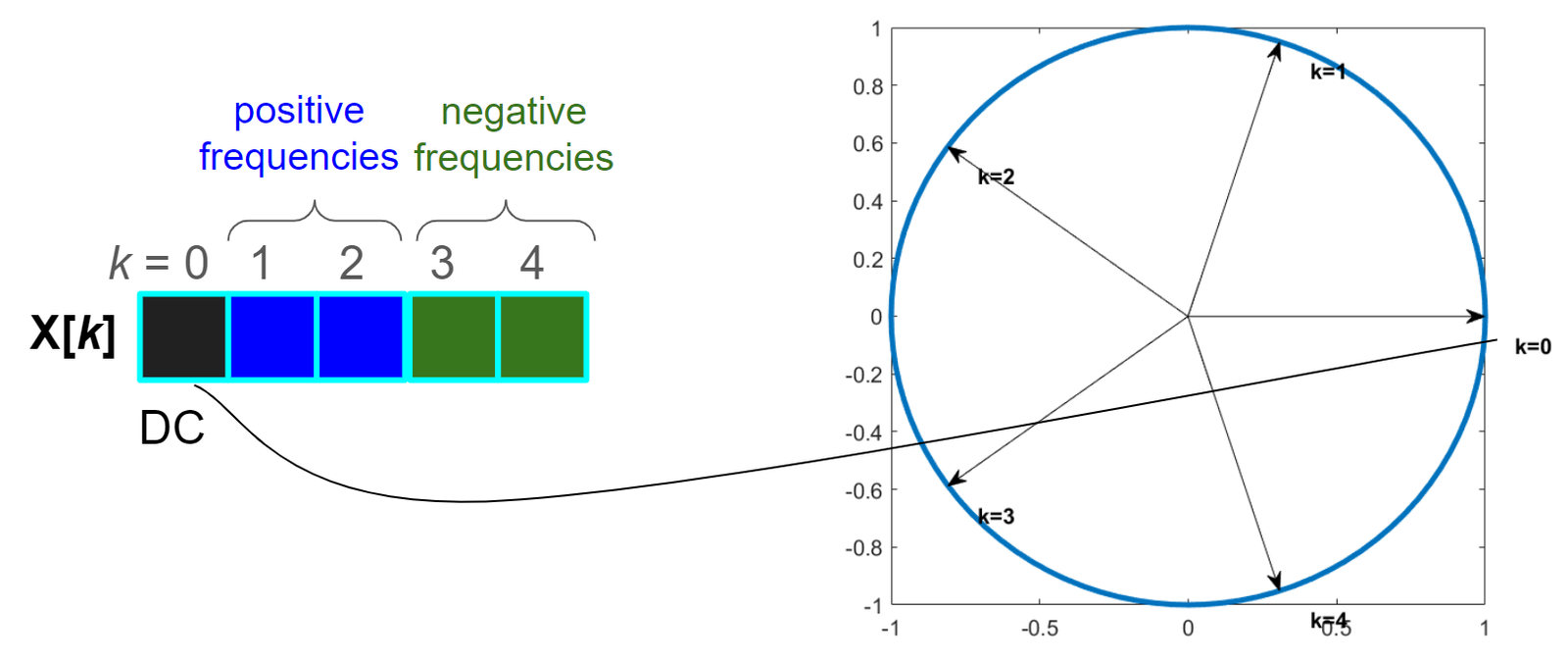
Assuming a DFT with points, Figure 2.5 indicates the angular frequency corresponding to each DFT coefficient . For instance, the DC coefficient corresponding to is the first element of the vector with DFT coefficients. For even, the Nyquist frequency is used and its respective coefficient is the element corresponding to .
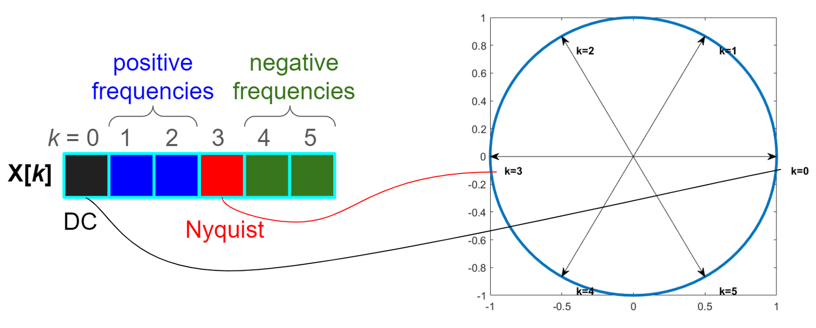
Figure 2.6 shows a figure similar to Figure 2.5 but for a DFT with points. In the case of an odd value of , the Nyquist frequency is not used in the DFT calculation.
Another aspect depicted by both Figure 2.6 and Figure 2.5 is that the negative frequencies are located after the positive ones in the DFT coefficients vector. The Matlab/Octave function fftshift can be used to move the negative frequencies to the first elements of this vector.
The -point forward and inverse DFT pair can be written as a pair of equations. The forward (direct) transform is
|
| (2.13) |
which corresponds to calculating the -th DFT coefficient as the inner product between the time-domain signal and the -th basis vector of Eq. (2.11) multiplied by . In this calculation, the adopted inner product for complex-valued vectors of Eq. (A.28) is responsible for Eq. (2.20) using instead of .
The inverse DFT transform equation is
|
| (2.14) |
Eq. (2.13) and Eq. (2.14) are the most adopted definitions of a DFT pair. But the DFT scaling factor in Eq. (2.21) can be changed to , and the same factor be also used in Eq. (2.13), if one wants to have a DFT pair with basis functions with unit norm. In this case the transform is called unitary DFT and has the properties already discussed in Section 2.4.1.7
Instead of using transform equations, sometimes it is convenient to use a matrix notation for transforms. With a matrix notation, it is easier to interpret Eq. (2.21) as composing the time-domain signal as a linear combination of basis functions scaled by the respective coefficient .
To develop the matrix notation, one can observe that an element of the -point inverse DFT matrix is given by
|
| (2.15) |
Because and appear in Eq. (2.15) as multiplication parcels, and the inverse DFT matrix is symmetric, that is .
For the sake of comparison, when , the inverse DCT and DFT matrices are, respectively:
The example shows that the inverse DFT matrix is symmetric, while the inverse DCT matrix is not. It can also be noticed that the inverse DFT matrix is complex-valued, having elements that are real and imaginary. In contrast, the inverse DCT matrix is real-valued. However, the first and third columns of are real-valued (all elements are or ). For , these rows correspond to and , which are called DC and Nyquist frequencies, respectively. All values corresponding to the basis vector of frequency (DC) are given by , as indicated in the first column of . And for even, all values corresponding to the basis vector of the Nyquist frequency (third column of ) are given by .
From Eq. (2.15) and adopting , the DFT inverse matrix is given by
Note that the complex numbers with angles and (which is equivalent to ) rad and magnitudes equal to 1, can be written as and , respectively. This simplifies writing the elements of for and other values of .
Example 2.8. Examples of 4-point DFT calculation. Let us calculate the 4-point DFTs of three signals represented by the column vectors , and . In this case, the forward and inverse matrices can be written as
respectively. The coefficient vectors are , and .
Because the basis functions (columns of ) are orthogonal, but not orthonormal, the -th coefficient of the forward transform is obtained by performing the inner product between and the complex conjugate of the -th basis function multiplied by .
The first basis function (corresponding to ) is always the first column of , which in this case is . Because all elements of this basis function are a constant ( when ), the job of the respective coefficient is to represent the average value (DC level) of the input signal. After multiplication by , the scaled basis function for is (first row of ) and the corresponding coefficients in , and are 8, 0 and 10, respectively. This indicates that the DC level of , and are 2, 0 and 2.5, respectively.
This example also illustrates the symmetry of DFT coefficients when the input signal is real-valued. One can note that the coefficients corresponding to and are complex conjugates, while the coefficients corresponding to and (more generally, , for even) is always real-valued. In fact, because the basis functions for frequencies (DC) and (Nyquist) are real-valued, if the input vector is also real-valued, these two DFT coefficients will always be real-valued (in the case is even).
The following example addresses the situation when is an odd number. In this case, the Nyquist frequency is not represented in the DFT values.
Example 2.9. Examples of 5-point DFT calculation. Let us calculate the 5-point DFTs of three signals that have five elements but are similar to the ones in the previous example: , and . In this case, the inverse matrix can be written as
which can be written in Cartesian form using two decimal places as
When , the DFT angular resolution is rad, which corresponds to degrees. To better visualize the involved angles, as a third altenative to denote , one can use the notation for complex values and use angles in degrees to write
Performing the direct transform, one finds that the coefficient vectors in this case are , and .
The first (DC) coefficients in , and are 10, 0 and 15, respectively. After division by , one can find that the DC level (or average value) of the time-domain vectors , and are 2, 0 and 3, respectively.
This example also illustrates the symmetry of DFT coefficients when the input signal is real-valued. One can note that the coefficients corresponding to and are complex conjugates, while the coefficients corresponding to and (more generally, , for even) is always real-valued. In fact, because the basis functions for frequencies (DC) and (Nyquist) are real-valued, if the input vector is also real-valued, these two DFT coefficients will always be real-valued (in the case is even).
On the symmetry of DFT coefficients when the input signal is real-valued
Figure 2.5 and Figure 2.6 are useful to observe symmetries related to the DFT transform. Starting from Eq. (2.12), if we substitute the original angular frequency by , the new basis is given by
|
| (2.16) |
Comparing with Eq. (2.12), one can note that is the complex conjugate8 of the function that has frequency . Therefore, if , in case one changes the sign of the angular frequency of from to to obtain a new basis function , the new coefficient has the property of being the complex conjugate of if is real-valued.
Observing Figure 2.5, the angles corresponding to and are opposites. Also, is the opposite of . Therefore, the respective pairs of DFT coefficients are complex conjugates. More specifically, and , when a 6-point DFT is adopted. Similarly, when assuming and following the mentioned reasoning, one can conclude from Figure 2.6 that and .
In general, if the input signal is real-valuded one has DFT coefficients with the complex conjugate property
If is even, this is valid for . And if is an odd number, the range is . The following example illustrates this fact.
Example 2.10. Coefficients that are complex conjugates when the signal is real-valued. All the time-domain input vectors of Example 2.8 and Example 2.9 are real-valued and can be used to help studying the symmetry of the respective DFT coefficients.
In Example 2.8, the coefficient vectors are , and . Recalling that the first element has index (not ), it can be seen that the coefficients corresponding to and are always complex conjugates.
Similarly, in Example 2.8, the coefficient vectors are , and , and one can observe that the coefficients corresponding to the pairs and are always complex conjugates.
The basis functions for the DC and Nyquist coefficients are real-valued9 Hence, another property of the DFT for real-valued inputs is that are real-valued coefficients for and, in case is even, . This can be observed in the DFT coefficients discussed in Example 2.10.
Advanced: DFT and FFT denoted with the twiddle factor
For convenience, the twiddle factor is defined as
|
| (2.17) |
such that the -th basis is for the conventional DFT and for the unitary DFT. Twiddle means to lightly turn over or around and is used because the complex number has magnitude equals to 1 and changes only the angle of a complex number that is multiplied by it. Each element of the inverse DFT matrix is
Hence, the twiddle factor denotes the DFT angular frequency resolution .
Figure 2.7 illustrates the complex numbers as vectors for different values of . Because , the twiddle factor is located on the unit circle of the complex plane and effectively informs an angle. For example, the three angles used by a DFT of points are 0, 120 and 240 degrees, while a 4-point DFT uses 0, 90, 180 and 270.
For , the DFT pair is given by
|
| (2.18) |
and
Note that because the basis functions have norms equal to (the DFT matrix was not defined as unitary). In this case,
|
| (2.19) |
Also note that the reason to have defined as a negative exponent in Eq. (2.17) is that the direct transform uses positive powers of . Another important fact is that for any . This can be seen by noting that has a period of samples and . Hence, the 4-point direct DFT matrix of Eq. (2.18) can be written as
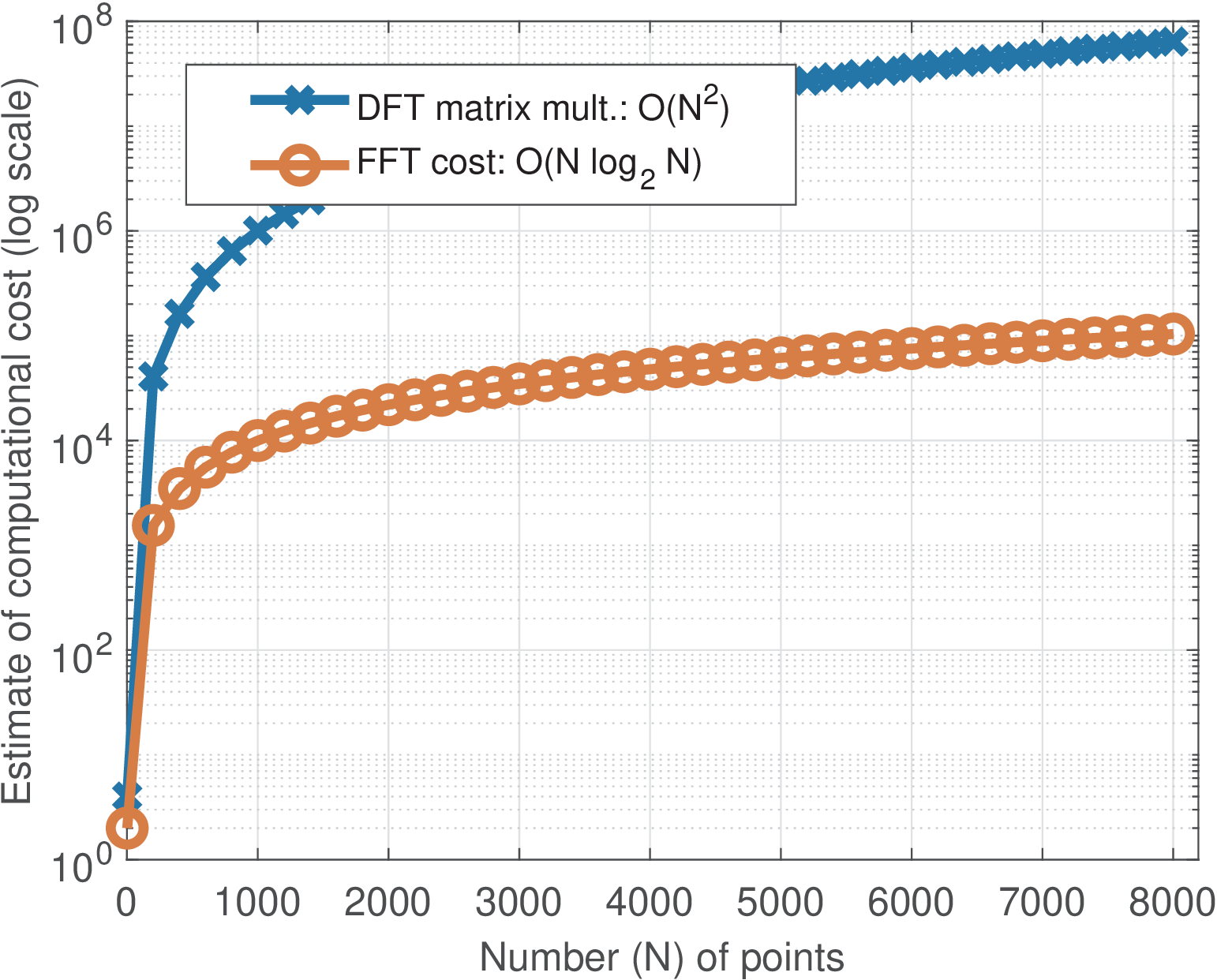
It can be seen that the matrix (and also ) has several symmetries that can be explored to save computations. There is a large set of algorithms for efficiently computing the DFT. These are collectively called fast Fourier transform (FFT) algorithms. Apart from numerical errors, both DFT (the plain matrix multiplication) and FFT algorithms lead to the same result. Therefore, the DFT is the name of the transform and FFT is a fast algorithm (from a large collection) used to speed up calculating the DFT. Implementing an FFT routine is not trivial but they are typically available in softwares such as Matlab/Octave.
There are FFT algorithms specialized in the case where the FFT size is a power of two (i. e., ). Other FFT algorithms do not present this restriction but typically are less efficient. The computational costs of DFT and FFT are quite different when grows large. The DFT matrix multiplication requires computing inner products, so the order of this computation is while FFT algorithms achieve . Figure 2.8 illustrates this comparison.
Instead of using matrix notation, one can use transform equations. The -point DFT pair (forward and inverse, respectively) is:
|
| (2.20) |
and
|
| (2.21) |
For the unitary DFT pair, the normalization factors should be changed to:
|
| (2.22) |
and
|
| (2.23) |
2.4.4 Haar transform
In signal processing, the Haar transform is intimately related to wavelets. This section will not explore this relation nor detail the generation law of Haar matrices. The goal here is to motivate the study of wavelets by indicating how basis functions with support shorter than can be useful.
The Haar transform is unitary, such that . The reader can use the script MatlabOctaveThirdPartyFunctions/haarmtx.m with A=haarmtx(N) to obtain the forward matrix . For , the Haar, DCT and unitary DFT forward matrices are all the same:
For , the Haar forward matrix is
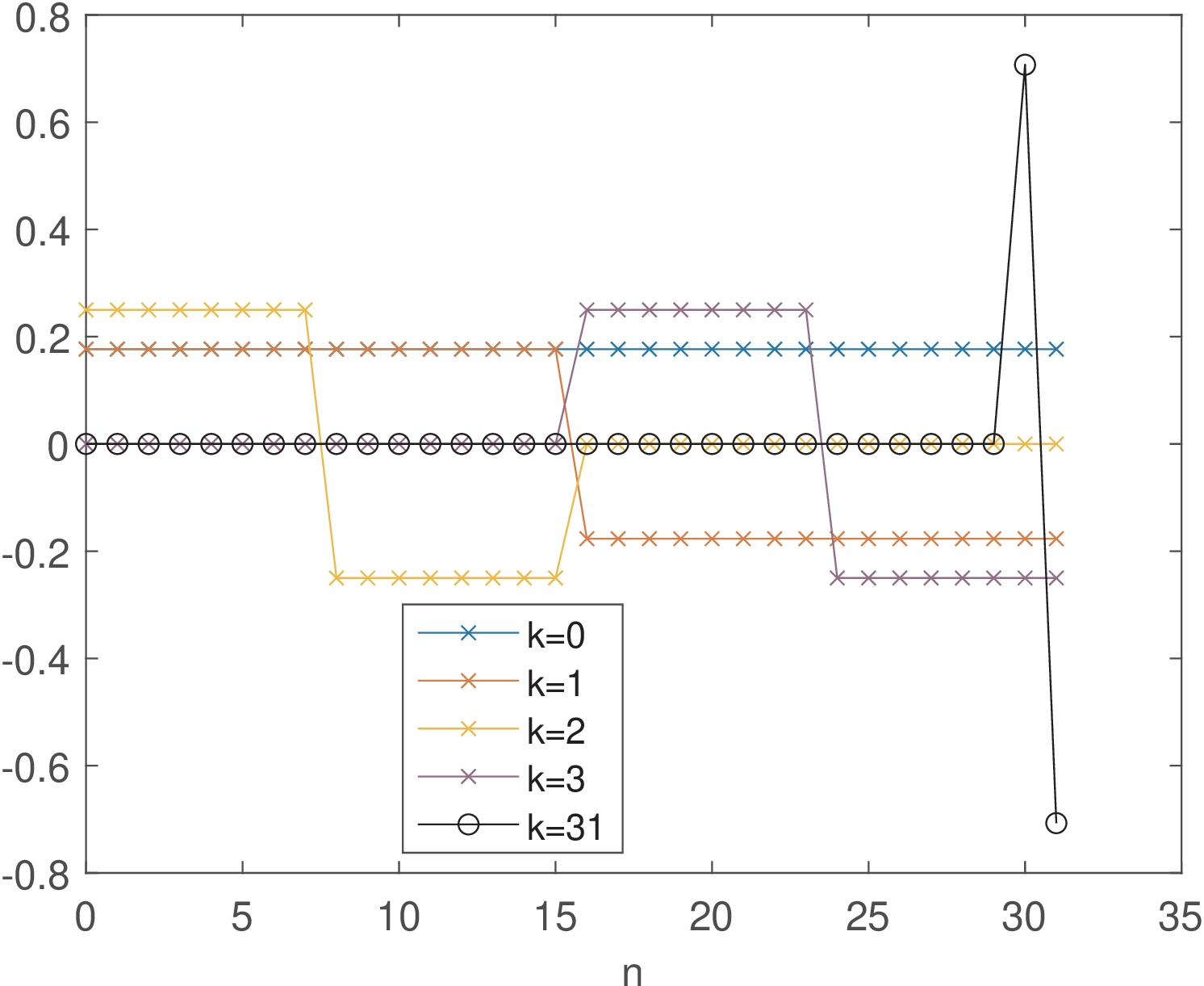
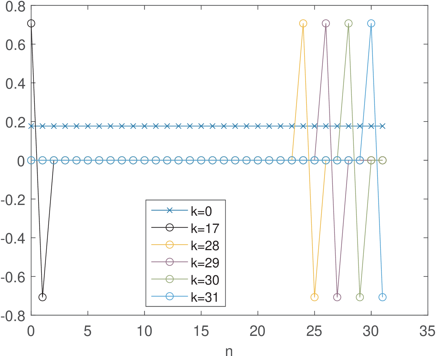
Figure 2.9 and Figure 2.10 depict some Haar basis functions. The most interesting aspect is that, in contrast to DCT and DFT, some Haar functions are non-zero only at specific intervals. This characteristic allows the Haar coefficients to provide information not only about “frequency”, but also about “time” (or localization). For example, it is well-known in signal processing that Fourier transforms are better suited for stationary signals while wavelets can better represent transient signals in a time-frequency plan. This kind of behavior can already be visualized by comparing DFT (and DCT) basis with Haar’s and is explored in Application 2.1.
2.4.5 Advanced: Properties of orthogonal and unitary transforms
As commented, for transforms with unitary matrices, is simply the inner product between and the -th basis function.10 In the inverse transform, the coefficient is the scaling factor that multiplies the -th basis function. This interpretation is not valid for a general non-unitary transform pair and .
The next paragraphs discuss the fact that unitary matrices do not change the norm of the input vectors. After that, the orthogonal transforms are compared to the unitary, to show that even when the norm of the basis vectors is not equal to one, the orthogonality still enables inverting a matrix using inner products.
Advanced: Unitary matrices lead to energy conservation
Another interesting property of a unitary matrix (or transform) is that it does not change the norm of the input vector, that is
As indicated in Eq. (1.69), the squared norm of a vector corresponds to its energy and, consequently, a unitary matrix conserves energy when is transformed into . The following example summarizes this result.
Theorem 2. Parseval’s theorem for unitary block transforms. If is unitary, the transform conserves energy () or, equivalently, .
Proof sketch: First, recall that
To visualize that , for simplicity, assume that and . Hence, and, because is unitary, and . Therefore, the squared norm is . Same reasoning applies for as indicated by Eq. (A.31).
Example 2.11. If the transform is unitary in a coding application, the total error energies in time and frequency domains are equal. In a coding application that uses a unitary transform, the error energy in time and “frequency” domains are the same. In other words, assume that is a unitary matrix and the original vector is obtained from the coefficients . If the original coefficients are encoded and represent an approximation , the error vector has the same norm of the error vector in time domain .
To better understand this fact, one can write:
|
| (2.24) |
The proof above uses the reasoning adopted in Eq. (A.31).
Advanced: Orthogonal but not unitary also allows easy inversion
Orthogonal but not unitary matrices also lead to useful transforms. They do not lead to energy conservation but the coefficients are conveniently obtained by inner products, as for unitary matrices. An important detail is that when used in transforms, the inner products with the basis vectors of a orthogonal matrix must be normalized by the norms, as discussed for the DFT. This aspect is further discussed in the sequel. The term “energy” is used here instead of vector “norm” because the results are valid not only for vectors, but also for continuous-time signals, for example.
An orthogonal matrix can be written as , where is unitary and is a diagonal matrix with the norm of the -th column of , or square root of its energy , composing the main diagonal. The inverse of a matrix with orthogonal columns is
Example 2.12. Inversion of orthogonal but not unitary matrix. For example, and form a basis for with energies and , respectively. The matrix with orthogonal columns can be written as , where is orthonormal. The inverse of is or, equivalently, .
If all columns of an orthogonal matrix have the same energy , its inverse is
|
| (2.25) |
Example 2.13. About the orthogonal (non-unitary) DFT transform. For example, in Eq. (2.11) or, equivalently, Eq. (2.20), the DFT transform was defined by an orthogonal matrix with the same energy for all basis functions. Therefore, Eq. (2.25) leads to , which is equivalent to Eq. (2.19).
The next section focuses in Fourier transforms and series. The connections with block transforms are plenty. For example, extending Eq. (2.25) for continuous-time signals, the basis functions for Fourier series, other than the one for , have energy over the duration of a fundamental period . Hence, the inverse transform in Eq. (2.27) has the factor .
